under construction.
ASSEMBLY and INSTALLATION of new
SAMI DISH.
Most of what's shown below, was actually done prior to removing the
Orbitron dish, and moving the old pole/concrete ball. I wanted to
basically align the mount prior to putting it up on the pole, so that
all I would need to do was to rotate the whole mount on the pole to
find the sats, then fine tune the elevation and mount on pole very
slightly to finish the alignment.
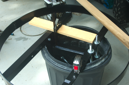
When I pulled the mount out of the box (very heavy), I decided to first
try to set the declination on the mount. (I recommend the so
called "modified declination".) Basically, to set the
declination, you need two surfaces on the mount, one parallel to the
rotation axis, and one perpindicular to the aim of the dish, and
measure the angle between those two surfaces. On the SAMI
mount with the 36" ring, the rotation axis is inside the square tube
that the carpenter's square is measuring to below, and the wooden board
is across part of the ring is perpindicular to the dish aim. What
I tried to do was to measure the distance between the board and the
square tube at 2 different points 10" apart, then the difference
between those two measurements divided by the 10" is the tangent of the
declination angle. I first calculated the difference in
measurements I needed, then adjusted the two big shiney bolts at the
right to adjust the declination. Later, I found a slightly more
accurate way of doing this, without crushing my trash can.
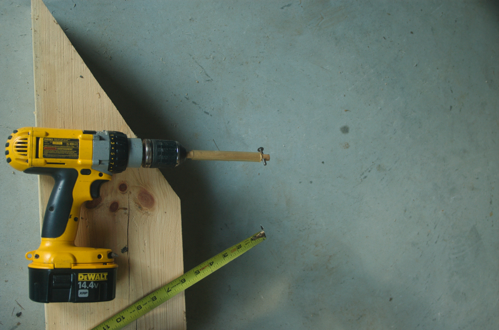
THEN, I decided to set the ring upside down on 3 wooden blocks. I
connected an old actuator to keep the mount part in place.
The actuator didn't have the motor on, which exposed the drive slot, so
I put a wooden dowel in a hand drill, and put a small bolt through the
end of the dowel that could fit into the drive slot of the actuator, so
that I could drive the actuator in and out with the power drill.
(If you do this with an acutator you're using, make sure you return the
actuator to the same point it was at when you took the motor off, or
else the limit switches won't be adjusted correctly.)
Anyway, first, I drove the actuator to it's
retracted position (without moving the saddle clamp on the actuator),
and checked the rotation angle. This angle is related to
the 90 degrees minus the actual angle around the rotation axis,
sometimes referred to as the USALS angle on small motorized Ku
systems.
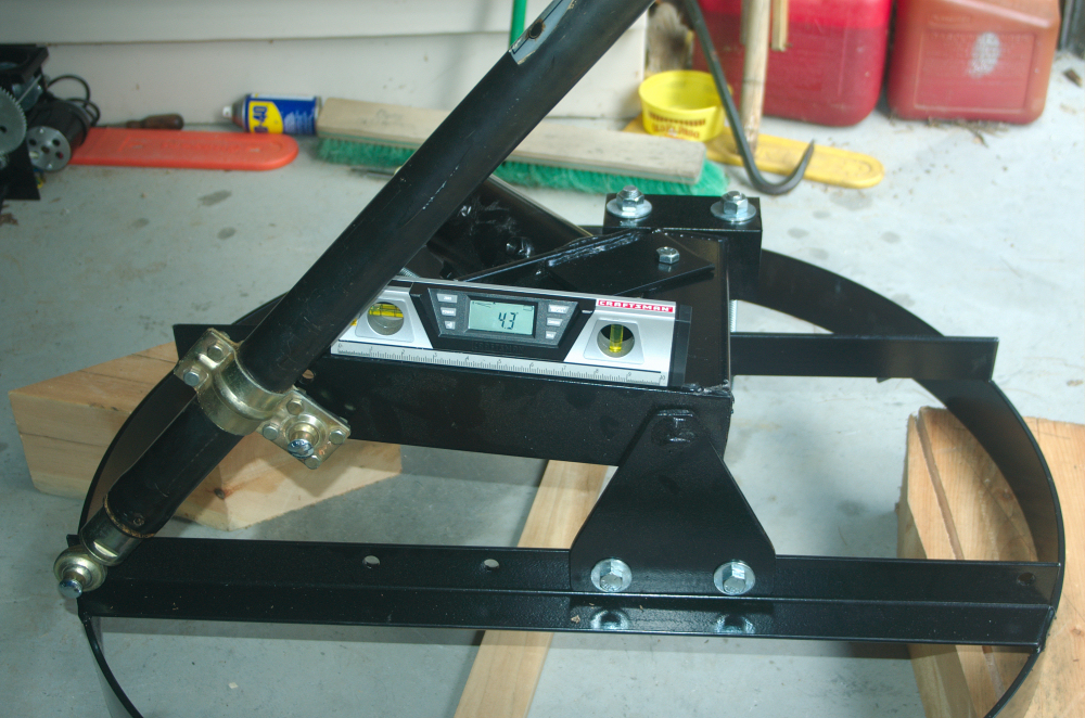
The indicated 4.3 deg was way too small, and would correspond to aiming
below the horizon, so I calculated the angle needed to give me an
elevation needed to see the lowest sat visible from my location, which
turned out to be around 20 deg, which corresponds to a 70 deg USALS
angle. I then slid the saddle clamp on the actuator to give me
approximately the 20 deg angle.
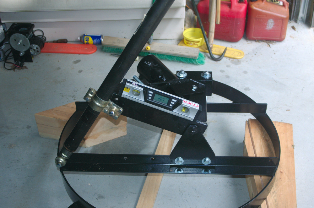
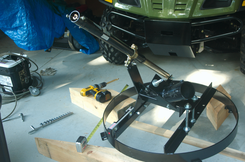
THEN, I decided to see how far this 24" actuator would take this
particular mount on extension.
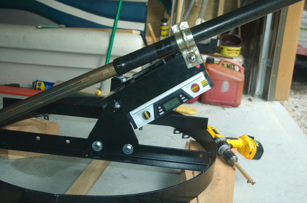
The above image shows that the 24" extension was more than enough to
take this mount as far as it can go without modifying the mount's
mounting points. The above illustrates why some people destroy
actuators by trying to drive their dish too far. Obviously, the
actuator could drive the dish this far, however when the actuator tries
to pull the dish back, it will be exerting an incredible force on the
actuator, and will often pull the insides out of the actuator before it
will move the dish. This is because the angle is so small that
almost all the force is applied perpindicular to the direction you are
trying to make the connection point on the dish move. Ie, to pull
the dish back, the connection point to the left (off the image) would
have to move nearly straight up, and yet the actuator is pulling it
horizontally. If that angle gets close to zero, you'd have to
destroy either the mount or the actuator for the actuator to retract,
and usually the actuator fails. But anyway, I demonstrated
that the actuator was capable of sending the dish fairly far past
vertical, although I intend to set software limits to keep it from
getting as far as pictured above.
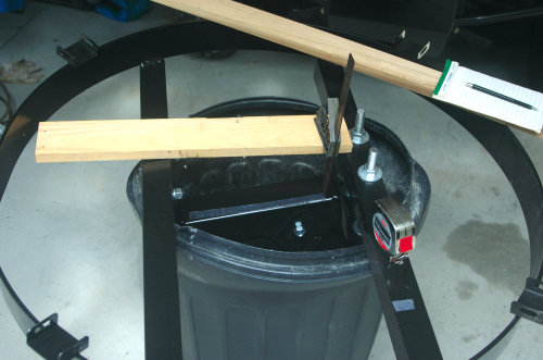
Then, below, I found an alternative, probably better way to
measure/adjust the declination. Here, I have the ring, which is
perpindicular to the dish aim on the wooden blocks, horizontal, zero
angle, and I put the angle meter on the square tube, which is the
rotation axis. The angle measured is the declination angle. Set
to the appropriate angle for my latitude.
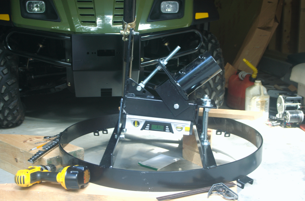
FINALLY, below, I set the angle meter on the part of the mount that
goes onto the pole, so that the angle measured corresponds to the
elevation of my true south satellite. Adjusted this with
the big bolt to the left of the level.
With this set, it SHOULD be just a matter of putting the mount on the
pole, putting the dish on the mount, then rotate the mount so it is
pointing south, and I should see satellites.
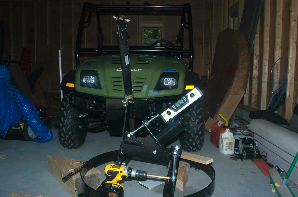
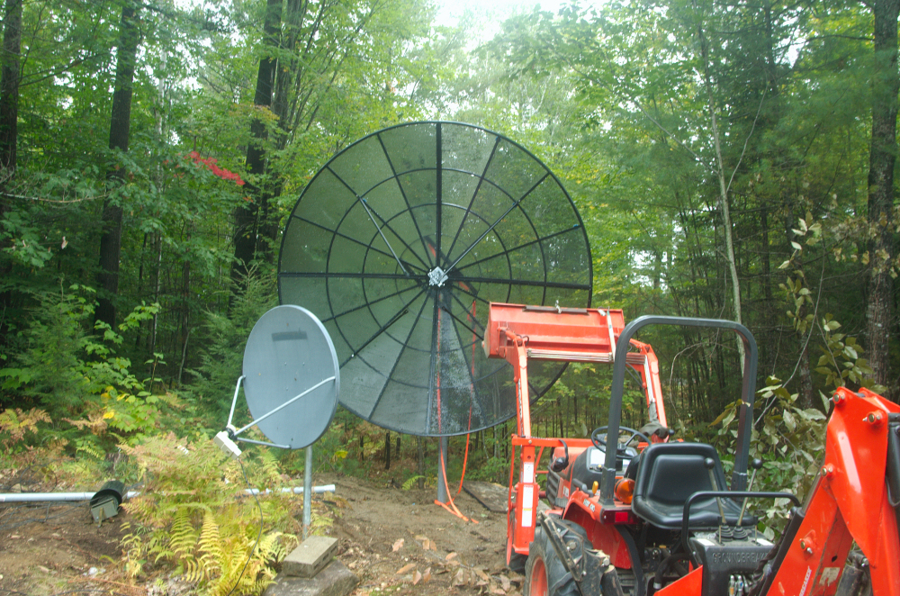
At this point, I put the mount in the bucket of my tractor,
and put the mount on the pole.
So, the NEXT step was to actually assemble the dish itself.
Sorry.... I forgot to take pictures of this.
I had intended to put the 4 dish sections up on the mount, one by one,
which was what I did with my first SAMI dish, some 20 years ago,
however the instructions said to put the dish together on a flat
surface and THEN put it up on the mount. So I decided to follow the
instructions. ???
The 4 sections bolted together, and also were bolted to the two
circular center plates, one plate above, and one below the mesh
sections. The first 3 sections went together fine, but to get the
bolts into the center plate on the last section, you have to be UNDER
the dish, and to connect the nuts, you have to be above the dish where
you can't reach. Also, you couldn't even reach the 2 bolts closest to
the center holding that last section to the other sections... so it
turned out that there was NO WAY to follow the instructions. I
ended up connecting the bolts that I could reach at the edge, then
lifted the dish up on edge to connect the bolts at the center, but even
that was hard for one person to do. But I got it connected.
THEN, however, it was too big and clumsy for me to get it out of my
garage by myself, so I had to ask my wife to help me tilt and carry it
through the garage door, and put it up on the mount, so now I can't say
that I did it all by myself. :-)
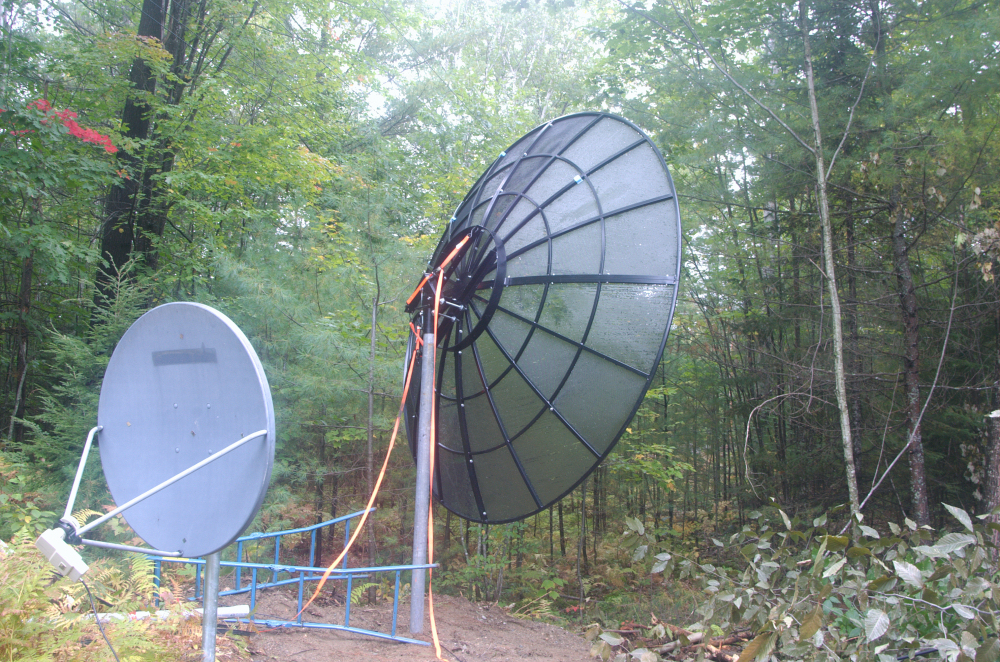
HOWEVER, once I got the dish up, I ran into yet one more problem.
The next step was to connect the feedhorn support arms. With my
FIRST SAMI, I was able to tilt the dish different directions, and was
able to reach the points where the arms connected, so I had planned to
do that with this new SAMI. I first tipped the dish
all the way over to the east side..... (I had hoped that
the orange straps would support the dish and keep it from going all the
way but that didn't work).
With the dish turned to the east, I connected the arms I could reach
from that side. (Sorry, fuzzy picture due to fog/humidity and
poor lighting)
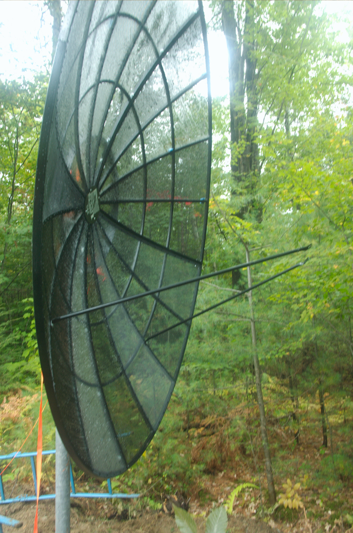
I thought that at this point I could connect the other two arms by
moving the dish over to the west.
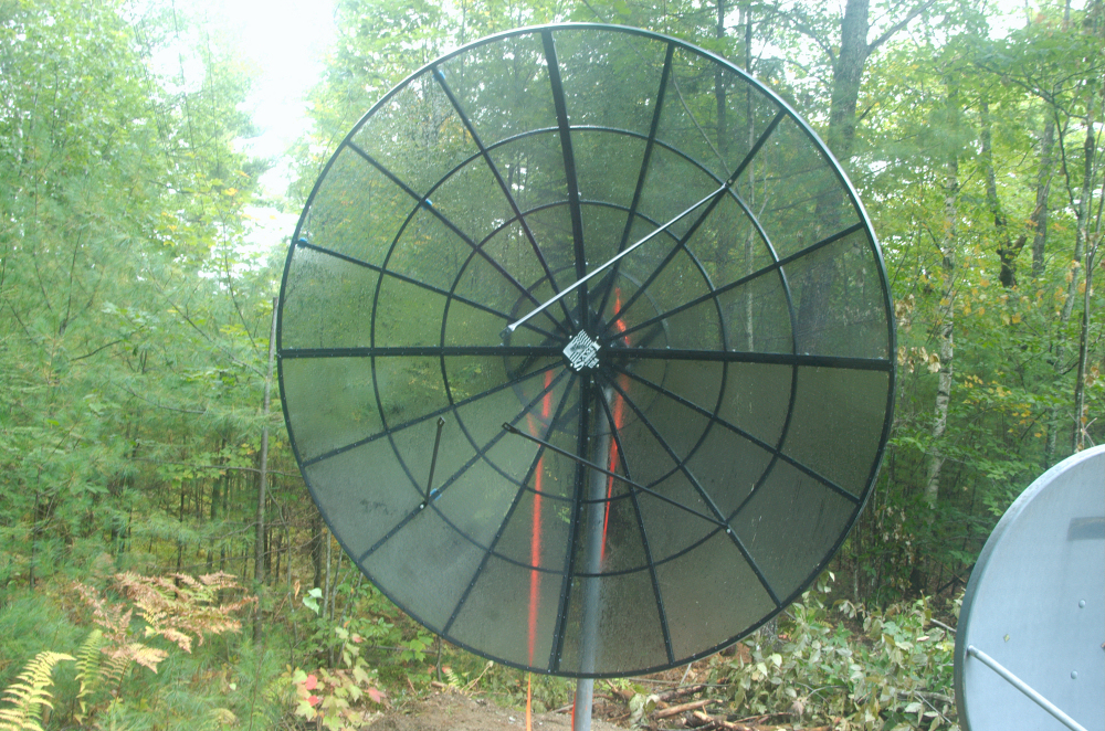
Unfortunately, I could only reach one more arm. The last arm was
way at the top.. With my OLD SAMI, I was able to reach it by releasing
the elevation rod, and tilting the dish over on it's back, but with
this mount, it was obvious that this wouldn't be enough to let me reach
the connection point. So I brought up my tractor again.
I got up into the bucket, and used a stick to push the hydraulic lever
to lift me up to where I could reach the connection point. Was a
bit flakey since there is a hydraulic leak on my bucket, and it keeps
drifting down, so I had to keep pushing the lift lever every minute or
so, but it worked fine.
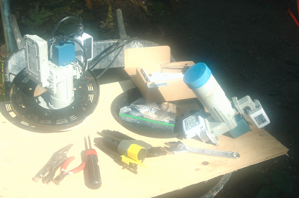
Next, above, I set up my feedhorn. Had to remove old Orbitron
plastic plate, put on the SAMI plastic plate, and I wanted to switch
one of my LNBs, so I set up a temporary table with a piece of plywood
on a wheelbarrow. (Sorry picture foggy due to fogged lens...
humid morning.)
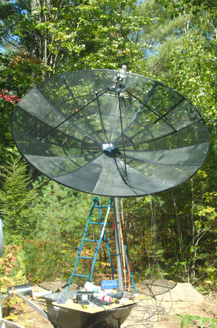
Finally, feedhorn connecte, and temporarily connected my old actuator
again, since I could move the dish with the hand drill as before.
Cables all hooked up temporarily routed, and ready to find
sats. I was in a hurry to find a satellite that I'd be
watching football on the next day, so I just turned the dish to where I
had previously determined that sat would be. At first I didn't
find the sat, but then I found that somehow I had rotated the feedhorn
90 deg, so all my H polarities were V, and visa-versa. Once I
corrected the polarity, I found the sat, and made some temporary fine
tune adjustments to get the sat for my NFL game. I'll
finish the alignment next week. :-)
UPDATE.... Welllll..... things didn't work out
_QUITE_ as well as I had hoped. The
in-the-garage pre-alignment got the alignment close enough to find the
sats, but it wasn't a very good alignment. After playing with it
a bit more, it seemed apparent that the problem was that some of the
surfaces I used to set angles weren't quite flat enough and parallel or
perpendicular enough with the rotation axis and aim of dish. Once
the dish was up, I found some better ways of placing my digital level
on the rotation axis so that it isn't influenced by some bumps caused
by welds. This allowed me to get the rotation axis elevation a
bit better. Then, I re-adjusted the two big bolts to get the
declination closer to what it should be. Tried the thing again,
and it was pretty close, but still not perfect. I can track C,
and Ku across the arc. Ku is better than it was with my old
Orbitron, but not as good as I get with my 90cm Primestar dish.
It's about the same as my 90cm Fortec. Ku SHOULD be better than
it is, however, so I still have some work to do. I think my next
step is to get the ladder up to the feedhorn and make sure the focal
distance is peaked.
I've had to put off further work on this temporarily,
however, due to a series of failures of other components, like coax
cables, diseqC switches, and the motor that runs my Fortec dish, plus I
needed to do some work burying the coax prior to winter, as I had
cables laying all over the ground in an area where I drive snowmobiles
and ATVs. Hope to get back to this soon, and when I do, I'll add
more pictures.